

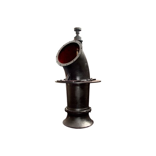
1000-1600HLB Vertical Mixed Flow Pump
1200-1600 HLB(Q) Type vertical semi(full) adjustable axial/mixed flow pump
- Advanced technology, excellent water conservancy performance, high efficiency
- Traditional type, no transmission shaft type structure
- Broad type spectrum range, complete model specifications
- General motor, both economical, simple and convenient maintenance
- Demonstration of the type
- Structure diagram
- Structural description
- The material of the main parts
1600HLB-50
1600HLQ-50
1600—vertical pump outlet diameter (mm, mm) HLB—vertical semi-adjusted mixed-flow pump HLQ—vertical fully-adjusted mixed-flow pump 50—1/10 of the pump specific speed ns, that is, 500 specific speed
When ordering, the installation angle of the water pump blades, unit installation form, installation elevation “L”, and supporting motor power, voltage, speed and other requirements must be clearly stated. Use additional text descriptions, which will not be reflected in the model number.
Product structure drawing II (withstand axial force of motor)

- Fully adjustable water pump
The fully adjustable water pump can adjust the installation angle of the pump blades without any assembly or disassembly; the mechanical adjuster is installed on the top of the motor or between the motor and the pump, and cooperates with the internal mechanisms of the impeller and pump shaft (motor shaft) to achieve full adjustment of the pump blades. Blade adjustment range: -20°-+4°. When the blade installation angle is set at -18°-20°, the water pump is started, and the starting torque is small and stable. After starting, the blade installation angle can be adjusted to the required working condition.
a) Top-mounted mechanical adjuster: The adjuster is installed on the top of the motor and requires a special motor with a hollow motor shaft. The adjustment axial force is borne by the motor layer.
b) Center-mounted mechanical regulator: The regulator is installed between the motor and the pump, and does not require a special motor with a hollow motor shaft. Adjust the axial force to the internal force of the pump. If users have requirements, we can also design and manufacture hydraulically controlled fully adjustable water pumps.
- Other structural descriptions
1) The pump station places the pump body on the water pump layer, the motor and transmission part on the motor layer, and a dedicated transmission shaft connects the motor and the water pump.
2) The weight of the motor, transmission part, pump rotor and the axial force of the pump water are borne by the motor layer, while the water pump layer only bears the weight of the pump shell components and other external forces during operation.
3) The water pump has two types of water pump layer installation structures: open (wet type) or closed (dry type). The pump is designed to be hoisted from the motor layer hoisting hole, making maintenance and installation easy.
4) The length of the transmission shaft can be configured according to the user’s different motor floor elevations. When the transmission shaft is too long, it is equipped with intermediate supporting components, and the pump station must have a corresponding supporting foundation.
5) When there are transmission components, there is a transmission shaft adjustment nut to adjust the center of the pump impeller.
6) The impeller has an adjustable structure. After the impeller components are removed, the blade placement angle can be adjusted.
7) The journal of the pump shaft and the water guide bearing is inlaid with a stainless steel sleeve, which has good wear resistance and anti-rust properties.
8) Shaft seal: The shaft seal is a packing seal, and the water seeping out of the packing is collected and discharged through the drain pipe.
9) Water bearing lubrication: In order to adapt to the sewage medium containing certain particles or impurities and protect the water bearing, a pump shaft sleeve is installed outside the pump shaft, and there are seals at the matching ends of the pump shaft sleeve. Generally, clean water with a pressure 0.2MPa higher than the pump head is injected through the water lubricating pipe on the upper part of the elbow, and the water bearing is lubricated and cooled from top to bottom and then flowed into the pump medium quality.
3.Special bolt sealing gasket: During closed (dry type) installation, a special bolt sealing gasket is placed between the connecting bolts of the guide vane body and the elbow, the hexagonal end of the hexagonal bolt and the contact surface of the elbow flange to prevent water from entering the pool. Leakage occurs through this bolt to the water pump layer.
4.Basic rings and pads:
For the horn water inlet type, a foundation ring (embedded parts) should be installed when the water pump layer is closed (dry type). The foundation ring and the water pump layer foundation are pre-embedded in a solid well as required to prevent water seepage. A seal must be placed between the water pump and its connecting surface. The pad (picture) prevents water from the inlet pool from penetrating into the water pump layer; in the convection channel water inlet method, the pump base structure is connected with the open type and the foundation pad. It is actually a dry device, so the water inlet is pre-embedded with the foundation ring and the pump inlet. All connections must take water seepage into consideration.
5.Others:
Straight pipes after the pump outlet elbow, 30° bent pipes, expansion joint components, etc. are all accessories for the pump, and the user can provide matching accessories according to needs.
- Regular supply:
Horn, guide vane body, elbow, impeller base, motor base, pump base: HT200/Q235
Pump shaft, transmission shaft: 45# steel;
Blade: ZG270~500
Water guide bearing: HT200+ natural rubber
Shaft seal: oil-impregnated graphite packing
- Optional supplies:
Blades: bronze, stainless steel
Impeller seat: bronze, stainless steel, ductile iron
Pump shaft: 2Cr13, 40Cr
Water bearing: HT200+polyurethane rubber/Salon
Other users will propose other materials for pump parts and they will be agreed upon at that time.
- Urban industrial and mining water supply and drainage, municipaProduct structure drawing II (withstand axial force of motor)l engineering, sewage treatment.
- Circulation and water upgrading in steel, metallurgy, power plants, shipbuilding, and water plants.
- Water conservancy projects, river management.
- Farmland irrigation, aquaculture, salt fields, etc.
- Single machine flow: 2.5m³/s—12m⁸/s.
- Lift: 2m–30 m.
- Pump water outlet diameter: 1200mm-1600mm.
- Transmission medium: clean water, river water, wastewater, rainwater, sewage and other liquids with similar physical and chemical properties to water.
- Matching motor:
Power supply: 380V, 660V, 6000V, 10000V 50Hz.
Protection level: IP23, IP44. Insulation level: Class B, Class F. Operating ambient temperature: 55°C; if the ambient temperature exceeds 40°C, reduce the power.
- Impeller steering: Looking down from the motor, the impeller rotates clockwise.
- Other instructions:
1) Water inlet form:
The horn water inlet is suitable for rectangular, polygonal, round, semicircular, volute and other water inlets.
2) Water outlet form:
HLB(Q) are 60° elbow water outlets with flange interfaces.
- The entire series has a wide range of models, complete models and specifications, and even and reasonable distribution of varieties. Suitable products can be found within the range to meet various working conditions.
- The pump has excellent hydraulic performance and high efficiency.
- Equipped with a general-purpose motor, it is economical, simple and convenient to maintain, and there is no risk of water intrusion from a submersible motor. It is safe and reliable.
- Main pump, transmission components (the motor does not bear axial force), motor (the user can purchase it by himself), and special tools
- Order clearly for closed installation: basic ring
- Clarify other special supply contents proposed by the user
- When ordering, please specify: product name and model, performance parameters (flow rate, head or blade installation angle, rotation speed, NPSHr), supporting motor and requirements, pump installation method, motor layer installation form, L – length, medium.
- Negotiate supporting parts: anchor bolts, flap doors, 30° elbow pipes, straight pipes, diffusion pipes, expansion joints and connecting bolts, etc., as well as requirements other than conventional supplied materials.
- Please contact customer service for details of type spectra, performance parameter curves, and appearance installation drawings.
30° pipe connection size

| R=1.OD | |||||||||||
| D | 350 | 500 | 600 | 700 | 800 | 900 | 1000 | 1200 | 1400 | 1600 | 1800 |
| R | 350 | 500 | 600 | 700 | 800 | 900 | 1000 | 1200 | 1400 | 1600 | 1800 |
| L | 47 | 67 | 80 | 94 | 107 | 121 | 134 | 161 | 188 | 214 | 241 |
| The flange size is the same as the outlet flange size of the corresponding pump. | |||||||||||
Door shape and connection dimensions
Floating box type flap door appearance and connection size table

| D | D₁ | D₂ | n-φd | a° | Kg |
| 300 | 395 | 440 | 12-φ23 | 15 | 82 |
| 400 | 495 | 540 | 8-φ23 | 22.5 | 90 |
| 500 | 600 | 645 | 12-φ23 | 15 | 101 |
| 600 | 705 | 755 | 12-φ27 | 15 | 148 |
| 700 | 810 | 860 | 12-φ27 | 15 | 180 |
| 800 | 920 | 980 | 12-φ27 | 15 | 240 |
| 900 | 1020 | 1075 | 12-φ27 | 15 | 315 |
| 1000 | 1120 | 1175 | 12-φ30 | 15 | 405 |
| 1200 | 1320 | 1380 | 12-φ30 | 15 | 448 |
| 1300 | 1430 | 1500 | 12-φ30 | 15 | 665 |
| 1400 | 1520 | 1575 | 12-φ30 | 15 | 891 |
| 1600 | 1760 | 1830 | 12-φ36 | 15 | Must contact the manufacturer |
| 1800 | 1970 | 2045 | 44-φ30 | 4.1 |
Counterweight door appearance diagram and connection dimension table

| D | D₁ | D₂ | n-φd | a° | Kg |
| 300 | 395 | 440 | 12-φ23 | 15 | 82 |
| 400 | 495 | 540 | 8-φ23 | 22.5 | 91 |
| 500 | 600 | 645 | 12-φ23 | 15 | 97 |
| 600 | 705 | 755 | 12-φ27 | 15 | 154 |
| 700 | 810 | 860 | 12-φ27 | 15 | 188 |
| 800 | 920 | 980 | 12-φ27 | 15 | 213 |
| 900 | 1020 | 1075 | 12-φ27 | 15 | 282 |
| 1000 | 1120 | 1175 | 12-φ30 | 15 | 330 |
| 1200 | 1320 | 1380 | 12-φ30 | 15 | 388 |
| 1300 | 1430 | 1500 | 12-φ30 | 15 | 649 |
| 1400 | 1520 | 1575 | 12-φ30 | 15 | 856 |
| 1600 | 1760 | 1830 | 12-φ36 | 15 | Must contact the manufacturer |
| 1800 | 1970 | 2045 | 44-φ30 | 4.1 |