

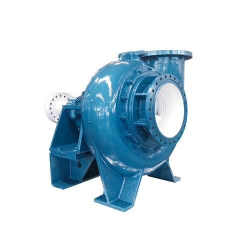
KDTX series desulfurization pump installation and operation manual
The KDTX series desulfurization pump is specially developed and developed by Shanghai Kaiquan Pump Industry Group for the auxiliary system of desulfurization and purification equipment in coal-fired power plants. It is mainly used as a pump for the auxiliary system of wet FGD equipment, used to transport limestone and gypsum slurry. This series of pumps adopts a single shell structure design, making the pump more compact, lightweight, and easier to maintain. In terms of hydraulic model design, structural design, and the use of wear-resistant and corrosion-resistant materials, it combines the advantages of similar products at home and abroad and innovates. Its various performance indicators exceed industry standards and are at the leading level in China. The technical conditions of the product comply with national standards.
KDTX series desulfurization pump installation and operation manual
- Model Meaning
- Structural Description

The impeller diameter is cut from 35cm to 34cm
Number of impeller blades A (A5, B4, C3, D2, 5 not marked) Pump outlet diameter 100mm
Kaiquan desulfurization pump
Horizontal axial suction, single stage single suction, single shell centrifugal desulfurization pump
The transmission mode of the pump is elastic coupling direct transmission.
Below, we will explain the pump head, shaft seal, and bracket parts separately.
- Pump head section
The pump head consists of components such as impeller, volute, rear guard plate, tailstock, and bracket. The snail shell is connected to the bracket with bolts or bolts. This series of pumps is a single shell structure, with the flow components (impeller, volute, rear guard plate) made of A49 material, and the tail frame/cover made of QT500-7 material.
The impeller is cast as a whole, consisting of front cover plate, rear cover plate, blades, and back blades. The leaves are twisted and usually have 5 leaves; The back blades are distributed on the outside of the front and rear cover plates, usually 8 pieces, and the impeller is threaded to the shaft. This series of pumps comes with a disassembly ring for easy disassembly of the impeller. Before operation, the hexagonal bolts on the disassembly ring should be sealed with butter to prevent rust.

Structural diagram of KDTX series single shell desulfurization pump
| Serial Number | name | Material | Serial Number | name | Material |
| 1 | impeller | A49 | 5 | mechanical seal | |
| 2 | volute | A49 | 6 | bracket | HT200 |
| 3 | Rear guard board | A49 | 7 | coupling | HT200 |
| 4 | Tail frame/tail cover | QT500-7 | 8 | base | Q235-A/HT200 |
From the drive end, the pump rotates clockwise
- Shaft seal section
This series of pumps adopts a mechanical seal type, consisting of a rear guard plate, mechanical seal, pressure cover, and shaft sleeve. The mechanical seal adopts a containerized structure. In order to provide a more detailed description of the mechanical seal, the mechanical seal structure and precautions can be found in the accompanying mechanical seal user manual and related materials.
- Bracket section
The bracket adopts a horizontally open and thin oil lubricated structural type.
It mainly consists of parts such as bracket body, bracket cover, shaft, bearing box, bearing, bearing cover, labyrinth sleeve, gear sleeve, dust disk, oil seal, dismantling ring, etc.
The large bracket design ensures smooth and reliable operation.
By using thin oil lubrication for the bearings, the working conditions of the bearings have been improved, allowing them to operate at lower temperatures and greatly increasing their service life.
Two oil markers are symmetrically arranged on both sides of the oil chamber of the bracket body. During operation, the oil level can be observed from the more convenient side according to the specific situation. The oil level should be located at the oil level line of the oil gauge.
Set the adjusting screw to adjust the clearance between the impeller and volute, ensure that the pump is easy to adjust during assembly and use, reduce the leakage at the inlet side of the impeller, and keep the pump in efficient operation.
KDTX150-40 and above pump models also come with a water cooling device.
By adopting modern CAD design methods and comprehensive hydraulic optimization, the gap between the baffle and impeller is increased, the wear of the baffle is reduced, the unevenness of the flow around the impeller is reduced, vibration and noise are reduced, efficiency is improved, and the service life of the pump is extended.
Adopting internationally leading sealing technology, leak free sealing effect, containerized structure, easy installation and replacement.
Serialized, large bracket, and large shaft diameter design ensure smooth and reliable operation.
Using wear-resistant and corrosion-resistant materials, with a long service life.
◇ Medium temperature: ≤ 80 ℃
◇ Solid liquid mixture concentration: ≤ 45%
◇ Flow range: 5-3000m ³/ H
◇ Head range: 3-110m
When lifting pumps with packaging boxes, steel wire ropes should be tied according to the markings on the packaging. When lifting, the bottom or side of the box shall not be subjected to impact or severe vibration, the packaging box shall not be excessively tilted, the packaging box shall not be placed on objects with sharp edges, and shall not be inverted.
Lift pumps without packaging boxes according to the following requirements:
(1) Lift the horizontal pump with a common base and motor, with the lifting center of gravity located near the coupling in the square hole of the bracket. The steel wire rope passes through this point and is vertically connected to the lifting hook. To maintain balance, an auxiliary lifting steel wire rope needs to be installed between the pump head or the motor lifting ring screw and the lifting hook. (See Figure 1a)
(2) When lifting a horizontal pump without a base or with a separate base, the lifting center of gravity should be near the pump head through the square hole of the bracket, and the steel wire rope should be vertically connected to the lifting hook through this point. To maintain the balance of the pump, an auxiliary lifting wire rope can be installed at the inlet short pipe of the pump. (See Figure 1b)
The lifting ring screws on the bracket cover are designed for dismantling the bracket and should not be used separately for lifting the overall pump to avoid accidents!

Figure 1 Schematic diagram of pump lifting method
- The contact area between the steel wire rope and the pump body should be protected with soft objects to prevent damage to the appearance of the pump or cutting of the steel wire rope.
- Installation
(1) Pre installation inspection
The pump has been inspected and tested before leaving the factory, and to ensure its good working condition, it must be installed correctly. Before installation, the equipment model and parameters should be checked according to the packing list to ensure they are correct, the components are complete and intact, and the accompanying technical information and quality certificate are complete. After verifying the accuracy, it is necessary to carefully read the relevant technical materials, especially the KDTX series desulfurization pump user manual, and master the relevant technical requirements and operating essentials before installation, avoiding blind operation.
(2) Installation and alignment of pumps
The horizontal pump unit should be installed using the secondary grouting method. After installation, the axis of the unit coincides with the vertical centerline of the foundation when viewed from above; The deviation between the center height of the unit and the design value should not exceed ± 2mm, and the level of the unit
The tolerance is 0.1/1000.
The coaxiality of the unit is generally ensured by the alignment of the coupling. There are two methods for aligning couplings:
One method is to use a knife edge ruler in conjunction with a feeler gauge. Align the outer circle of the coupling with a knife edge ruler to ensure that each pair of couplings is flush in all directions, with the maximum error δ It should not exceed 0.10mm. (See Figure 2a). Check the gap between each pair of couplings with a feeler gauge, and the maximum error △ should not exceed 0.10mm (△= δ 2- δ 1) (See Figure 2b).
Another method is to use a magnetic dial gauge in conjunction with a feeler gauge to align the coupling. Fix the magnetic dial gauge on the outer circle of one coupling and turn it. Place the dial gauge probe on the outer circle of the opposite coupling and observe that the runout of the dial gauge should not exceed 0.15mm. (See Figure 2c). The clearance of the coupling should be measured with a feeler gauge, and the maximum error should not exceed 0.10mm

Figure 2 Alignment of Coupling
(3) Configuration and requirements of pump inlet and outlet pipelines
① Inlet pipeline
Inlet pipe diameter: The inlet pipe diameter should be the same as or slightly larger than the inlet diameter of the pump. The principle is to avoid cavitation of the pump and prevent sedimentation of the slurry in the pipeline.
Inlet gate valve: In order to facilitate pump maintenance, an inlet gate valve should be installed with the same diameter as the inlet pipe. An expansion joint should be installed between the inlet of the pump and the inlet pipe to facilitate the disassembly and assembly of the pump.
② Discharge pipeline
Discharge pipe diameter: The discharge pipe diameter is related to the properties of the slurry and the settling flow rate. Generally, the discharge pipe diameter is equal to or slightly larger than the outlet diameter of the pump.
Export gate valve: The export gate valve should have the same diameter as the discharge pipe.
Pressure gauge: located on the straight pipe section between the pump outlet and the first valve.
③ Precautions for pipeline configuration: The pipeline configuration is shown in Figure 3

Figure 3 Pump inlet and outlet pipelines
The size of the pipe diameter should consider comprehensive factors such as system resistance and the critical settling velocity of the slurry. The inlet pipe should be as short and straight as possible. At the inlet of the pump, it is best to equip a straight pipe section with the same diameter as the inlet, and its length should not be less than 3 times the inlet diameter (the flow rate inside the inlet pipe is generally 1.5-3m/s). It depends on the settling flow rate of the transported slurry.
When using a high-level layout, the inlet pipeline of the pump should avoid forming steam pockets, and it is recommended to use a horizontal upper busbar
The variable diameter pipe is shown in Figure 4.
When adjusting the flow rate with a valve, the regulating valve should be located at the pump outlet, and it is not allowed to adjust it with a valve on the inlet pipeline to avoid cavitation.

Figure 4 The upper busbar is a horizontal variable diameter pipe
(4) The pipeline configuration and requirements for shaft seal water and cooling water should be configured according to Figure 5.
KDTX150-40 and below pump types have no cooling device and do not add cooling water.
The pressure and flow requirements of the shaft seal water are detailed in the mechanical seal user manual.

Figure 5 Configuration of shaft seal water and cooling water
(5) Mechanical seal
Mechanical seal is a type of end face seal. It has the characteristics of no leakage and low power consumption. The mechanical seals used by our company are manufactured by professional mechanical seal manufacturers and have been installed and debugged before leaving the factory. Users will no longer need to perform debugging.
Special attention should be paid to the following issues when using mechanical seals for slurry pumps:
① Before using the pump, it is necessary to first connect the shaft seal water, then start the pump, stop the pump for 5-10 minutes, and then turn off the shaft seal water When the pump and mechanical seal spare parts equipped with mechanical seals are not used for a long time, the mechanical seal part should be filled with HL46 hydraulic oil to prevent internal rust of the mechanical seal components and failure of internal rubber parts.
(6) Requirements for filling lubricating oil
Add HL32 (winter) or HL46 (summer) hydraulic oil according to the oil level line on the oil level gauge before driving. Avoid driving without fuel!!!
- Pump adjustment
The pump should be inspected and adjusted after installation and alignment.
(1) The inspection and adjustment of the clearance between the impeller and volute can be found in Chapter 5.
(2) Adjustment of motor steering
The rotation of the motor should ensure that the pump’s rotation is consistent with the specified direction and should not rotate in the opposite direction, otherwise it may cause the impeller to trip or even damage other components.
When adjusting the direction of rotation of the motor, it should be done in a completely disconnected state from the pump (i.e. without the coupling pin), and only after confirming that the direction of rotation of the motor meets the requirements can it be connected to the pump. Blindly starting the motor is absolutely not allowed!
(3) The adjustment of the transmission device should correctly install the pin components and protective covers. (See Figure 5)
Figure 5 Installation diagram of elastic column pin coupling
(4) Tighten all fasteners once with a wrench.
(5) Clean up tools and debris placed on the unit to prevent accidents during operation.
- Trial operation of the pump
After the pump unit is installed and debugged, it can be put into trial operation. Users with conditions should first use clean water for trial operation, and then transport the slurry after normal operation.
(1) Start of single-stage pump
① Open the shaft seal water and cooling water, and adjust the pressure to the specified value;
② Fully open the inlet valve;
③ Open the water injection valve to inject water into the pump (the backflow pump does not require water injection);
④ Adjust the opening of the outlet valve to 1/4;
⑤ Start the unit. After the rotational speed is normal, open the outlet pressure gauge. If the pressure is normal and stable, slowly open the outlet valve until it is fully opened or meets the operating requirements.
Attention: Starting the pump with the outlet valve fully open will cause the motor to overload; Using a smaller inlet valve to control flow can cause pump cavitation, which should be avoided!!!
(2) Starting the series pump
The delivery pipeline of the series pump is relatively long, and the design and calculation of the head are based on the consideration of running the entire pipeline full of slurry. When the pump is started, the pipeline is not filled with slurry. If the valve is fully opened, the head of the pipeline is very low, and the instantaneous flow rate of the pump tends to be large, causing motor overload or pump cavitation vibration, leading to faults. It is advisable to start according to the following steps:
① Close the outlet valve and fully open the inlet valve;
② Open the shaft seal water and cooling water, and adjust the pressure to the specified value;
③ Open the water injection valve to inject water into the pump (open the inlet valve of the backflow pump);
④ Start the first stage pump and gradually open the outlet valve to 1/i (i is the series stage);
⑤ When the slurry is estimated to be filled to 1/i of the pipeline, start the second stage pump and gradually open the valve to 2/i;
⑥ When the slurry is estimated to be filled to 2/i of the pipeline, start the third stage pump and gradually open the outlet valve to 3/i;
⑦ Repeat the process until the slurry fills the entire pipeline and operates normally.
(3) Precautions when starting the pump:
① A pump equipped with a water injection type mechanical seal, without shaft seal water, will instantly burn due to dry friction between the dynamic and static rings
Destroy.
② After normal operation, the following items should be observed:
- Is the shaft seal water supplied to the mechanical seal normal? The temperature rise of the mechanical seal is ≤ 35 ℃, and the maximum temperature is ≤ 75 ℃.
- Whether the flow head (inlet and outlet pressure) of the pump is stable and meets the process requirements;
- Is the current stable;
- Is there any abnormal noise or excessive noise or vibration in the unit;
- Is the shaft seal leakage normal (dripping); Mechanical seal specification size ≤ 50mm, leakage rate ≤ 3ml/h; When the size of the mechanical seal is greater than 50mm, the leakage rate is ≤ 5ml/h.
- The temperature rise of bearings is generally around 35 ℃, and the maximum temperature should not exceed 75 ℃.
(4) Stop pump
① Before stopping the pump, clean water should be pumped for 30 minutes to clean the slurry inside the pump and pipe.
② Close the outlet valve of the final stage pump.
③ Starting from the final stage pump, stop the pump step by step from the first stage pump, and close the corresponding shaft seal water and cooling water.
④ Close the inlet valve of the first stage pump.
Attention: Do not stop all pumps at the same time when the outlet valve is fully open! Otherwise, it is easy to form water hammer, causing damage to the pump or pipe fittings.
The KDTX series desulfurization pump has been adjusted before leaving the factory, and users do not need to disassemble and inspect unused pumps within 6 months after purchase. Just check if the rotation is flexible, if there is rust, and if there is oil filling. To ensure the safe and reliable operation of KDTXT series desulfurization pumps, daily maintenance and the use of correct repair and disassembly methods are crucial. Therefore, based on the characteristics of this series of pumps, we propose the following maintenance and repair requirements for user reference.
- Keep the equipment clean, dry, oil-free, and leak free.
- Check the oil level inside the bracket daily to ensure it is appropriate. The correct oil level should be near the oil level line and should not exceed ± 2mm.
- Regularly check for abnormal sound, vibration, and leakage during pump operation, and promptly address any issues found.
- It is strictly prohibited to operate the pump in an empty state, as the pump not only vibrates violently in an empty state, but also affects the pump’s lifespan. Special attention must be paid.
- It is strictly prohibited to enter metal objects and large solid blocks that exceed the pump’s allowable passage inside the pump, and it is also strictly prohibited to enter flexible materials such as rubber, cotton, and plastic to avoid damaging the flow components and blocking the impeller flow channel, which may cause the pump to malfunction.
- Regularly check whether the pressure and flow rate of the shaft seal water and cooling water are appropriate. The method of checking the opening degree of the shaft seal water pipe valve or detecting the temperature at the rear protective plate machine seal can be used: when the temperature is high, it indicates insufficient water supply.
- Regularly check that the maximum temperature of the bearing should not exceed 75 ℃.
- After the first 800 hours of continuous operation of the pump, the lubricating oil should be completely replaced once, and after that, the lubricating oil should be replaced every 1500 hours of operation.
- The standby pump should rotate 1/4 turn per week to evenly withstand static loads and external vibrations on the shaft.
If the shutdown time is long, the pump should be flushed with backwash water to flush the sediment inside before starting again.
- Regularly check the fastening of the support mechanism of the inlet and outlet pipeline system to ensure reliable support. The pump body should not bear supporting forces.
- Regularly check the fastening of the pump on the foundation, and the connection should be firm and reliable.
Special attention: For newly installed and repaired pumps, it is necessary to first test the direction of the motor before putting on the coupling pin. Do not drive the pump in reverse by the motor. But it is allowed that in the event of a power outage of the motor, the liquid in the pipe can reverse and cause the pump to reverse. However, it should be noted that when the height difference is particularly large (≥ 80m), it is necessary to prevent backflow of return water to control sudden pump reversal.
Before starting the pump, the shaft seal water and cooling water should be turned on first, and then the pump should be turned on. After stopping the pump for 5-10 minutes, the shaft seal water should be turned off.
To ensure the efficient operation of the pump, it is necessary to adjust the clearance between the impeller and the front guard plate regularly (after using it for a period of time, when the current slowly decreases under unchanged operating conditions) to maintain it between 0.75 and 1.00 mm. The adjustment steps are as follows:
The gap between the impeller and the front guard plate is 0.75-1.00mm, which is usually adjusted before leaving the factory. If this gap does not meet the requirements, it should be adjusted. If any problems are found during operation, the machine should also be shut down for adjustment. The adjustment method is as follows:
① Loosen the clamping nut of the bracket cover;
② Loosen the adjustment screws of the bearing housing;
③ Evenly tighten the compression nuts of the bearing box to move the rotor assembly towards the pump head direction, and turn the machine while tightening,
Until the disc stops moving. Pay attention to the direction of the turning gear and follow the working direction of the pump.
④ Measure the gap between the bearing housing flange and the bracket end face using a feeler gauge δ= A; At this point, the gap between the impeller and the front guard plate is 0.
⑤ Loosen the compression nut of the bearing box;
⑥ Evenly tighten the adjustment screws of the bearing box to move the rotor assembly towards the motor direction. Use a feeler gauge to check the gap until δ= A+(0.75-1.00) mm (take the maximum value for large pumps), and ensure that the gap is uniform and consistent; ⑦ Tighten the bearing box compression nut to fully fix the axial position of the rotor.
| Serial Number | Part Name
|
Number of units per unit
|
amount
|
Material remarks |
| 1 | impeller | 1 | A49 | |
| 2 | volute | 1 | A49 | |
| 3 | Rear guard board | 1 | A49 | |
| 4 | Tail frame/tail cover | 1 | QT500-7 | |
| 5 | Dismantling ring | 1set | 2Cr13 | |
| 6 | bearing | Outsourcing | ||
| 7 | mechanical seal | 1set | Outsourcing | |
| 8 | O-shaped sealing ring | Fluororubber | Outsourcing | |
| 9 | oil seal | 2 | Nitrile rubber | Outsourcing |
| 10 | Front gear sleeve | 1 | 45 | |
| 11 | Deflector | 1 | HT200 | |
| 12 | Rear labyrinth sleeve | 1 | QT500-7 |
Note: The above vulnerable parts are not within the scope of “three guarantees”.
| Serial Number | failure mode | Cause analysis | Exclusion method |
| 1 | Pump does not discharge slurry, pressure
Power meter pointer drama Strong jumping or internal movement Abnormal voice |
1. The weight concentration of the slurry is too high | 1. Dilute the slurry |
| 2. The impeller and volute are severely worn | 2. Replace the impeller and volute | ||
| 3. The slurry input is lower than the process requirements | 3. Increase the feed volume or decrease the discharge volume | ||
| 4. Blocked inlet pipeline or insufficient valve opening | 4. Clean the pipeline or open the inlet valve | ||
| 5. Insufficient slurry input or generation of empty pump | 5. Increase the amount of slurry or temporarily add clean water | ||
| 6. Air enters the water inlet | 6. Eliminate the cause of air intake | ||
| 2 | Motor overload | 1. Excessive slurry weight concentration | 1.Reduce the weight concentration of the slurry |
| 2. Excessive traffic | 2. Increase the resistance of the outlet pipeline | ||
| 3 | Pump vibration is high
High noise level |
1. Pump cavitation occurs | 1.Identify and eliminate the cause of cavitation |
| 2. The pump shaft and motor shaft are not concentric | 2. Adjust the concentricity of the two axes | ||
| 3. Bearing damage | 3. Replace bearings | ||
| 4. Excessive medium flow rate and high temperature | 4. Increase the resistance of the outlet pipeline | ||
| 5. Loose fasteners or foundations | 5. Tighten the bolts and reinforce the foundation | ||
| 4 | Shaft seal water
Excessive leakage |
1. The pressure of the shaft seal water is too high | 1. Adjust the pressure of the shaft seal water |
| 2. Damaged machine seal | 2. Replace the machine seal | ||
| 5 | Leakage of slurry at the shaft seal | 1. The shaft sleeve is severely worn | 1. Replace the shaft sleeve |
| 2. No shaft seal water added or the pressure of the shaft seal water is too low | 2. Increase shaft seal water or increase shaft seal water pressure | ||
| 6 | Insufficient traffic
or Insufficient head |
1. The volute and impeller are severely worn | 1. Replace the impeller or volute |
| 2. The cavitation margin of the pipeline is less than the necessary cavitation margin of the pump | 2. Transform pipeline equipment to increase pipeline cavitation margin | ||
| 3. The weight concentration of the slurry is too high | 3. Reduce the weight concentration of the slurry or replace it with a larger diameter pump | ||
| 4. Scar formation in the water outlet pipeline | 4. Remove scar inside the tube | ||
| 7 | bearing
fever |
1. The pump bears the weight of the pipeline | 1. Adjust the pipeline bracket to prevent the pump from bearing the weight of the pipeline |
| 2. High vibration | 2. Check and eliminate the cause of vibration | ||
| 3. The pump shaft and motor shaft are not concentric | 3. Readjust the concentricity of the two axes | ||
| 4. Improper use or deterioration of lubricating oil | 4. Replace lubricating oil | ||
| 5. Bearing damage | 5. Replace bearings | ||
| 8 | Bearing components
Oil leakage |
1. The oil level is too high | 1. Lower the oil level |
| 2. Rubber component failure | 2. Replace the rubber parts | ||
| 9 | Pump not running | 1. The snail shell is silted up by solid and hard sediment | 1. Remove blockages |
| 10 | Pump head leakage | 1. The adhesive part is not properly pressed | 1. Reassemble or tighten |