

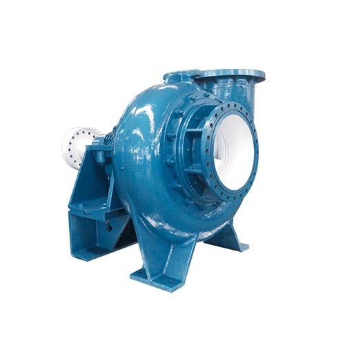
KQTL Desulfurization Pump
The KQTL (R) series desulfurization pump is a single-stage single suction horizontal centrifugal pump developed and developed by Kaiquan Pump Industry Group for the desulfurization and purification device of coal-fired power plants. It is mainly used as a circulating pump in the absorption tower of wet FGD equipment, conveying limestone and gypsum slurry. The product draws on the characteristics of similar products both domestically and internationally, and has advantages such as wide flow range, safe and reliable operation, convenient maintenance, high efficiency and energy conservation, and long service life.
- Model Meaning
- Structural characteristics
- Desulfurization conditions
- Material List
- Structural diagram
- Disassembly and assembly method
- Installation method


Adopting modern CAD design methods, combining binary theory design with two-phase flow theory design, the impeller is optimized by CFD hydraulic model design, with a reasonable structure, excellent overall performance, stable operation, and high efficiency.
The oil chamber seal of the bracket adopts advanced dynamic sealing concept, which is wear free and leak free.
Imported bearings, lubricated with thin oil bath, high-end configuration, and longer bearing service life.
The impeller is equipped with balancing holes, which minimize the pressure difference between the front and rear cover plates of the impeller and extend the service life of the bearings.
The unique stainless steel split impeller disassembly ring makes it easy to disassemble and assemble the impeller.
The rotor components are equipped with an axial adjustment structure to ensure that the pump unit always operates efficiently.
The pump has a rear detachable structure, which is simple in structure and easy to maintain, without the need to disassemble the inlet and outlet water pipes of the pump.
Special desulfurization pump seal, internationally leading containerized sealing technology, leak free sealing effect, making installation and replacement more convenient.
Multiple structural types are available, including double shell rubber lined and single shell all metal, to maximize customer satisfaction.
The temperature rise of bearings is measured using platinum thermistors, and the bearing temperature is monitored online.
The diaphragm coupling is used for connection, with a large axial adjustment margin, good dynamic balance performance, strong impact resistance, and large torque transmission, which can ensure smooth and safe operation of the pump.
| material | Main components | mechanical properties | Performance Introduction | Similar to Brands | ||||
| Code | C | Cr | Ni | Mo | δb(MPa) | HRC | ||
| A49 | 1-2 | 26-30 | 2-3 | 2-3 | ≥610 | HB≥400 | It has the good corrosion resistance of dual-phase steel and the wear resistance of high-chromium white iron. It has good use effect in environments containing chloride ions. | Cr26Ni2Mo2Cu1.5 (F30%CrMo) |
| 2605N | ≤0.03 | 26-28 | 4.5-6.5 | 3-5 | ≥670 | HB≥270 | Duplex stainless steel has good corrosion resistance and wear resistance, which is equivalent to CD4MCu in the United States. It has better use effect in desulfurization environment. | 1.4460 |
| 2507 | ≤0.03 | 24-26 | 6-8 | 3-5 | ≥730 | HB≥270 | It has excellent resistance to pitting corrosion, crevice corrosion and uniform corrosion | 1.4410 |
| 2205 | ≤0.03 | 22-23 | 4.5-6.5 | 3-5 | ≥670 | HB≥270 | It has excellent resistance to stress corrosion cracking, especially in environments containing chloride ions. | 1.4462 |
Figure 1: Single shell type

Applicable to: 550-900 caliber
| Serial Number | name | Materials | Materials | name | Materials |
| 1 | bracket | 6 | Pump body | 2605N | |
| 2 | Impeller disassembly ring | 4Cr13 | 7 | Front guard board | A49 |
| 3 | Shaft sleeve | ZG0Cr18Ni12Mo2Ti | 8 | impeller | A49 |
| 4 | mechanical seal | 9 | suction cover | QT500-7+rubber | |
| 5 | Rear guard board | A49 | 10 | Splicing board | QT500-7 |
Figure 2: Single shell type
Applicable to: 300-500 caliber
| Serial Number | name | Materials | Serial Number | name | Materials |
| 1 | impeller | A49 | 5 | Splicing board | QT500-7 |
| 2 | suction cover | A49 | 6 | Impeller disassembly ring | 4Cr13 |
| 3 | Pump body | A49/2605N | 7 | mechanical seal | |
| 4 | Rear guard board | A49 | 8 | Bracket components |
Figure 2: Double shell rubber lined type

Applicable to: 600, 700, 800 caliber
| Serial Number | Name | Materials | Serial Number | Name | Materials |
| 1 | impeller | A49 | 7 | Rear guard board | Natural rubber |
| 2 | suction cover | A49 | 8 | Splicing board | QT500-7 |
| 3 | Pump cover | QT500-7 | 9 | Shaft sleeve | 0Cr18Ni12Mo2Ti |
| 4 | Pump body | QT500-7 | 10 | Impeller disassembly ring | 4Cr13 |
| 5 | Front protective cover | Natural rubber | 11 | mechanical seal | |
| 6 | Rear protective cover | Natural rubber | 12 | Bracket components |

After removing the extended coupling, the rotor can be extracted as a whole without moving the pump body and bracket.
A rear pull suspension structure can be adopted, and an extended diaphragm coupling can be used. The entire set of rotor components can be extracted from the rear of the pump body, making disassembly and maintenance convenient. Especially when replacing vulnerable parts such as mechanical seals, there is no need to disassemble pipelines and motors. Simply remove the extended diaphragm coupling and extract the rotor, which is convenient for users to maintain and repair.


This series of pumps is mainly used as absorption tower circulation pumps in wet FGD devices. It can also be used to transport liquids containing corrosive and small solid particles in industrial sectors such as metallurgy, mining, coal, and chemical industry. It can also be used for municipal sewage discharge and river dredging.


1、 Main installation matters:
- Refer to the foundation load diagram and installation diagram provided by the manufacturer for foundation construction
- Select suitable shims for adjustment purposes
- The base must be leveled according to the standard of 0.1mm/500mm
- Machine leveling must comply with special specifications: the general assessment is as follows: 1. a-a ‘1. < 0.1mm, (b+b’)/2 < 0.15mm
- Install flushing and collection pipelines
- A dismantling short pipe should be installed at the pump inlet, and the specific dimensions can be found in the pump’s external dimension diagram
- Add support to the inlet and outlet pipelines, and it is prohibited to use pumps to support the weight of the pipelines. At the same time, a filter should be installed on the inlet pipeline.
2、 Pump start and stop
The rotation direction of the pump is clockwise when viewed from the drive end. Prohibit reverse operation!
Before starting the pump, it is necessary to carefully read the user manual and the manual for supporting equipment such as mechanical seals, reducers, and diaphragm couplings!
①Preparation work before startup
Check if the anchor bolts are tightened
Check if the bearing temperature control device is working properly
Check the insulation resistance of the motor
Check the oil level in the bearing oil chamber. The oil level should be level with the center of the oil gauge or added to the slope of the dipstick rod
Check if the mechanical seal positioning plate is loosened
Disconnect the electric coupling, check the motor direction, and connect the coupling properly
Rotate the rotor according to the rotation direction of the pump, without any friction, otherwise adjust the impeller clearance
②Start
Open the mechanical seal cooling water valve
Open the inlet valve of the pump
Open the air valve in the outlet pipeline of the pump
When the pump is filled with slurry, close the air valve
Start the pump
Gradually open the outlet valve (>1 minute)
③Normal shutdown
Close the outlet valve of the pump (for more than 1 minute)
Stop pump
Open the flushing valve
Close the inlet valve
Open the discharge valve within 1 minute after closing the inlet valve
Simultaneously open the air valve
After rinsing for 10 minutes or when only clean water flows out, close the discharge valve
If the pump is stopped for more than 24 hours, open the flushing valve and fill the pump with clean water
Close the flushing valve and air valve
④Abnormal shutdown
Gradually close the inlet valve, with a delay of more than 1 minute
Close the outlet valve
Open the discharge valve
Simultaneously open the air valve
Open the flushing valve
After flushing and discharging for 10 minutes or when only clean water flows out, close the discharge valve
If the pump is stopped for more than 24 hours, open the flushing valve and fill the pump with clean water
Close the flushing valve and air valve

Attention: Keep the oil level at the center of the oil gauge
- Maintenance of the bracket
Normally, 32 mechanical oil is added to the thin oil lubrication bracket; When the ambient temperature of the bearing is high, 46 # or 68 # mechanical oil can be added. When refueling, the oil level should be level with the center of the oil gauge or added to the slope of the dipstick rod. Do not add too much oil to prevent the heat generated by the bearing during normal operation from not being dissipated in a timely and effective manner, which may cause the bearing temperature to be too high. Normally, after the first cumulative operation of 300 hours, the lubricating oil should be replaced. Before adding new lubricating oil, the bearings and oil chamber should be thoroughly cleaned. After normal operation, when the bearing temperature is below 50 ℃, it is recommended to change the oil every 3000 hours of operation. When the bearing temperature is above 50 ℃, it is recommended to change the oil every 2000 hours of operation. (Users can also determine the oil change interval based on actual usage experience)
The operating temperature of bearings generally does not exceed 75 ℃.
The axial clearance of bearings generally does not need to be adjusted. As long as they are assembled in the correct order, their axial clearance is guaranteed.
2.Adjustment of impeller
In order to ensure the efficient operation of the pump, it is necessary to adjust the gap between the impeller and the front guard plate in time. The gap between the impeller and the suction cover of the pump should be between 2mm.
When adjusting the gap, stop the pump first, screw the mechanical seal limit plate into the positioning groove, and loosen the mechanical seal set screw; loosen the bolt compressing the bearing assembly, loosen the adjusting bolt nut 1, and tighten the nut 2. At the same time, Press the rotating wheel of the pump to turn the rotor until the impeller rubs against the suction cover, then tighten nut 1; then loosen nut 2, tighten nut 1, and rotate 1/3 turn according to the pitch of 3.5mm. Tighten the mechanical seal positioning screw and unscrew the positioning plate. After adjustment, check whether the impeller rotation is normal and whether the bearing assembly holding down bolts and adjusting bolts are tightened before starting again.
3. The standby pump should rotate the shaft 1/4 turn every week so that the bearings can evenly bear the static load and external vibration. If the pump is parked for a long period of time, the accumulated water in the pump should be drained, and the machined surfaces such as bearings, shafts, couplings, etc. should be treated with rust prevention.
| Fault | reason | Solution |
| The pump does not output liquid | ① There is air left in the pump and suction pipe ②The pressure in the suction pipe is less than or close to the vaporization pressure ③Air leakage in pipeline ④The speed is too high or too low ⑤The total head of the device does not match the head of the pump ⑥The specific gravity of the medium is different from the original design ⑦ There is debris blocking the pump or pipeline. |
① Refill the pump and remove the air ② Lower the installation height, reduce the resistance of the suction pipe, and increase the inlet pressure ③Check and tighten ④Determine the speed according to the performance point ⑤ Try to reduce the resistance of the discharge system ⑥Conversion should be carried out ⑦ Check and clean |
| Insufficient flow head | ① There is air left in the pump and suction pipe ②The suction lift is too high or the filling height is not enough ③The pressure in the suction pipe is less than or close to the vaporization pressure ④Pipeline leakage ⑤The speed is too high or too low ⑥The total head does not match the pump head ⑦The medium weight and viscosity do not match the original design ⑧The gap between the impeller and the suction cover increases ⑨ There is debris blocking the pump or pipeline. |
① Refill the pump and remove the air ② Lower the installation height, reduce the resistance of the suction pipe, and increase the inlet pressure ③Increase pressure ④Check and tighten ⑤According to the instructions ⑥ Try to adjust the pipeline resistance ⑦Conversion should be carried out ⑧Readjust ⑨Inspect and clean |
| Power consumption is too high | ①The speed is too high ②The total head does not match the pump head ③The specific gravity of the medium does not match the original design ④The pump shaft is inconsistent with the axis of the prime mover, and the shaft is bent ⑤The rotating part collides with the fixed part ⑥The gap between the impeller and the suction cover increases ⑦There is too much oil or too dirty in the bearing box |
①According to the instructions ② Try to adjust the pipeline resistance ③Conversion should be carried out ④Correction or replacement ⑤Adjust the gap ⑥Readjust ⑦Add or replace oil according to the oil level gauge. |
| Bearing overheating | ① Too much or too little lubricating oil ②There are impurities in the lubricating oil ③Bearing damage |
①Adequate refueling ②Replace ③Replacement |
| Bearing life is short | ①The pump shaft is inconsistent with the axis of the prime mover, and the shaft is bent ② The rotating part collides with the fixed part ③The impeller is unbalanced ④There are impurities in the lubricating oil |
①Correction or replacement ②Readjust ③Replace the impeller ④Replace |
Methods of flue gas desulfurization
With the development of industry in our country, air pollution control has attracted more and more attention. The pollution caused by sulfur dioxide and its hazards have become an increasingly important environmental issue that people are concerned about. Therefore, controlling the emission of sulfur dioxide from coal-fired boilers is of great significance for controlling air pollution and improving the ecological environment.
1、 Classification by presence or absence of liquid phase intervention
In the power industry, especially in the desulfurization industry, the methods of flue gas desulfurization are classified based on the presence or absence of liquid phase intervention, mainly including wet method, semi dry method, dry method, electron beam method, and seawater method.
①Wet process
Wet desulfurization is a method of using alkaline solution as a desulfurizer and applying absorption principle to desulfurization in gas, liquid, and solid phases. The desulfurization product and residual liquid are mixed together to form a viscous fluid. The operating temperature for wet desulfurization is between 44-45 ℃

②Semi dry method
Semi dry desulfurization refers to a desulfurization method in which liquid and gas phases are involved, and the desulfurization product is in the form of dry powder. The operating temperature for semi dry desulfurization is between 60-80 ℃.

③Dry method
Dry desulfurization refers to the method of completely dry desulfurization without liquid phase intervention. If dry quicklime or limestone powder is sprayed into the furnace, the desulfurization product will be in powder form. The operating temperature for dry desulfurization is between 800-1300 ℃.

④Seawater method
Seawater desulfurization is limited by geographical conditions and suffers from severe corrosion of equipment by chlorides. The pH value of the desulfurization residue is very low, and a water quality recovery system with reasonable parameters must be configured to meet the discharge conditions required by environmental protection.
⑤ Electron beam method
Electron beam method is a method that utilizes high-energy physics principles, uses electron beam irradiation of flue gas, or uses pulse generated corona to desulfurize the flue gas. The desulfurizer used is synthetic ammonia, which is currently limited to desulfurization of flue gas from small tonnage coal-fired boilers.