

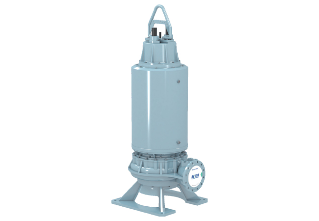

WQH Series(Semi-open Impeller) Submersible Sewage Pump
The WQH series submersible sewage pumps feature a semi-open impeller design, with fewer blades and a wider flow channel, facilitating the discharge of solid particles and long-fiber debris. The products comply with the national standard GB/T24674-2021 “Submersible Electric Pumps for Sewage and Waste”. Standard configuration includes winding temperature monitoring, bearing temperature monitoring, oil chamber leakage protection, motor cavity leakage protection, and junction box leakage protection (frame size 520 and above). When the motor is equipped with a closed-loop cooling system, models 30kW and above are equipped with a vibration sensor for vibration monitoring and protection. A smart data acquisition module (30kW and above) can also be added, integrating IoT technology to achieve online detection, fault warning, remote monitoring, energy efficiency management, full lifecycle maintenance, and equipment operation and maintenance management.
Furthermore, comprehensive optimization designs have been implemented in mechanical structure, sealing, and online monitoring, resulting in higher configuration, superior hydraulic performance, greater versatility, and better reliability.
The water pump motor can also be equipped with a unique closed-loop cooling system, which has strong heat dissipation capacity, achieves a lower liquid level when the pump stops, and the water pump can also be installed and operated in a dry manner.
WQH Series(Semi-open Impeller) Submersible Sewage Pump
High Passability
Adopting a semi-open impeller design, the wide flow channel allows for high passability of solid particles or long fibers.
High Configuration
Standard configuration includes SKF bearings, Burgmann mechanical seals, H-class motor insulation, and wear-resistant ductile iron impeller and pump cover.
High Reliability
Unique motor cooling circulation design, short pump shaft extension, self-cleaning mechanical seal technology, and double cable seals.
Universal Design
Modular pump design and standardized motor design ensure high versatility.
Smart Cloud Monitoring (Optional for 30kW and above)
Real-time data acquisition and transmission to a smart cloud platform for pump vibration, bearing temperature, winding temperature rise, and pump seal failure, enabling remote monitoring.
Optional Motor Cooling Method
When the pump requires a lower starting liquid level and the motor operates in dry mode, an optional motor cooling jacket can be added to improve motor heat dissipation.
- Explanation of performance curves and key parameters
- Model Description
- Installation Methods
- Wiring Method
- Main Applications
- Operating Conditions
- Pump main configuration

| Main parameters: Discharge port diameter 250mm | |||
| Pump model | Motor rated power (kW) | Speed (r/min) | Rated current (A) |
| 250WQH2315-608-75 | 75 | 990 | 142 |
| Motor power factor cosφ | Motor efficiency (%) | Stalled torque / Rated torque | Pump weight (kg) |
| 0.86 | 93.7 | 2.0 | 990 |
The solid line portion of the curve in the graph represents the recommended operating range of the pump. Shaft power increases to a certain value and then stops increasing. Pumps without overload generally do not pose a risk of overload; even if occasional overload occurs, it is limited. Therefore, the motor is safe to use such pumps at any flow rate. However, it is best to use them within the recommended range, as the pump efficiency is higher and more economical within this range. When the flow rate is less than the left limit, the unit efficiency is very low, generating large radial forces, leading to key rolling and shaft breakage. When the flow rate is greater than the right limit, the pump will experience vibration, noise, and other problems.
The maximum size of solid objects passing through the pump is specified in the “WQH Series Self-Cooling Circulating Submersible Sewage Pump Performance Parameter Table”.
Pump weight does not include accessories for various installation methods, such as coupling devices, fixed bases, pipe bends, and hose bends.

In impeller numbering, the last two or three digits are the sequence number, and the preceding digits indicate the number of motor stages. For example, in 657A, “6” indicates a 6-stage motor, “57” is the sequence number, and the “A” or “B” after the number indicate a cutting impeller. Similarly, in 1057, “10” indicates a 10-stage motor, and “57” is the sequence number.
Rated Voltage and Rated Frequency: The rated voltage of the motor is 380V, and the rated frequency is 50Hz.
The WQH series submersible sewage pumps are available in automatic coupling installation (Z). When the motor has a cooling system, it can be installed in either a dry horizontal installation (G-W) or a dry vertical installation (G-L). Both installation methods are simple. These are described below.
Automatic coupling installation (Z)

Automatic coupling installation essentially uses a coupling device to connect the pump and pipeline. With this coupling device, the pump and outlet pipeline are independent of each other, eliminating the need for conventional fasteners. Therefore, connecting and disconnecting the pump from the outlet pipeline is very easy. The coupling device is quite simple, consisting of only four components: an outlet pipe seat, a guide rod, a guide rod bracket, and a coupling frame. The guide rod only serves a guiding function and is not subjected to force; ordinary tap water pipes or steel pipes are sufficient, and users can provide their own. These pipes can also be easily cut to the required length according to the pool depth. During installation, assemble the outlet pipe seat, guide rod, and guide rod bracket. Attach the coupling frame to the pump body, lift the pump, insert the semi-circular opening on the coupling frame into the guide rod, and slide the pump down the guide rod to the bottom. The coupling frame will then lock the pump body and outlet pipe seat together, automatically aligning the pump outlet and outlet pipe seat inlet, and automatically sealing the flange face. When pump maintenance is needed, simply lift the pump upwards; the pump body and outlet pipe seat will then disengage. This installation method is truly worry-free, labor-saving, and convenient.
Because the coupling device and the pump are relatively independent, if your pumping station needs to be replaced with a pump of the same diameter but lower or higher head due to changes in circumstances, you can still use the original coupling device.
Dry horizontal installation (G-W) (with motor cooling system)

1. The water pump is horizontally supported and fixed by a pump bracket and a motor bracket. Both the pump bracket and motor bracket have mounting holes for fixing the water pump to the ground.
2. The water pump suction port is equipped with an inlet pipe. One end of the inlet pipe connects to the pipeline via a flange, and the other end connects to the pump via a flange, connecting the water pump and the pipeline.
3. The water pump has an intermediate support at the connection seat. When the water pump malfunctions and needs maintenance, the volute casing can be removed, and the motor section has a separate support.
Optional sliding rail mounting

Installation
1. First, connect and secure the water pump via the inlet flange and inlet pipe.
2. Adjust the adjusting bolts on the motor bracket to ensure the pump is level for easy installation.
Disassembly
1. First, secure the pump using the intermediate bracket and connecting seat, then connect the hydraulic device to the intermediate bracket.
2. Insert the side rails and adjust the adjusting bolts to ensure the weight of the motor is supported by the rails.
3. Loosen the pump body connecting bolts. The hydraulic device allows the motor to easily detach from the volute via the rails for easy maintenance and repair.
Note: Rails, hydraulic device, and intermediate bracket are priced and shipped separately if needed.
Dry vertical installation (G-L) (with motor cooling system)

1. Vertical dry installation is an installation method where the pump’s centerline is perpendicular to the ground. This method can be used when the customer lacks sufficient horizontal installation space, and the pump is fixed to the ground using a fixed base.
2. Vertical dry installation involves connecting the pump to the ground via a suction bend at the bottom of the pump.
Rotation direction: Viewed from the pump inlet, the impeller rotates counterclockwise.
Motor winding lead wire connection method:
For pumps of 55kW and below, use the inner delta (△) connection. This connection is pre-installed in the wiring cavity at the factory. Direct starting, autotransformer reduced voltage starting, or external electronic soft starter starting can be used depending on the site conditions (if the control cabinet uses star-delta starting, this must be noted on the order).
For pumps of 75kW and above, the six winding lead wires are directly connected to the six power conductors of the two main cables, using an outer delta (△) connection. This is suitable for autotransformer reduced voltage starting or external electronic soft starter starting. Alternatively, the six power conductors can be connected to the six copper busbars of the control cabinet, suitable for star-delta starting.
Mainly used in sewage treatment plants, municipal sewage lifting pump stations, waterworks, water conservancy and irrigation projects, water diversion projects, integrated pump stations, etc., for pumping sewage, wastewater, and rainwater containing solids and long fibers.
1. Medium temperature not exceeding 40℃, medium density ≤ 1050 kg/m³, pH value within the range of 4~10.
2. Minimum operating liquid level: See “▽” (standard configuration) or “▼” (available) in the installation dimension drawing (motor cooling system).
3. The main components of the pump are made of gray cast iron and ductile iron. It cannot be used to pump highly corrosive media or media containing highly abrasive solid particles. The impeller can be made of 2Cr13, 304, 316, etc.
4. The diameter of solids in the medium should be smaller than the minimum dimension of the flow channel. For specific solid dimensions, please refer to the “WQH Series Submersible Sewage Pump Performance Parameter Table”.
5. The length of fibers in the medium should be smaller than the pump’s outlet diameter.
| 11kW-22kW Configuration Table | |||
| Serial Number | Name | Material | |
| 1 | Impeller, pump cover | QT500 | |
| 2 | Pump body, casing, connecting seat, motor top cover | HT250 | |
| 3 | Shaft | 2Cr13 | |
| 4 | Motor insulation | 180℃ Class H insulation | |
| 5 | Bearing brand | SKF | |
| 6 | Mechanical seal | Brand | Burgmann |
| Motor-side friction pair | Graphite/Silicon Carbide | ||
| Pump-side friction pair | Silicon Carbide/Tungsten Carbide | ||
| 7 | O-ring | Nitrile-40 | |
| 8 | Cable seal | ||
| Configuration Table for 30kW and Above | |||
| Item | Name | Meterial | |
| 1 | Impeller, Pump Cover | QT500 | |
| 2 | Pump Body, Housing, Motor Upper Cover, Junction Box Cover, Connecting Seat, Upper Bearing Cover | HT250 | |
| 3 | Shaft | 2Cr13/3Cr13 | |
| 4 | Sealing Ring | HT250 | |
| 5 | Motor Insulation | 80℃ H-Class Insulation | |
| 6 | Bearing Brand | SKF | |
| 7 | Mechanical Seal | Brand | Burgmann |
| Motor Side Friction Pair | Graphite/Silicon Carbide | ||
| Pump Side Friction Pair | Silicon Carbide/Tungsten Carbide | ||
| 8 | O-ring | Nitrile 40 | |
| 9 | Cable Seal | ||
11kW-22kW Structural Diagram (Standard Configuration)

| 1 | Suction end pump cover | 8 | Cable |
| 2 | Pump body | 9 | Wiring tray |
| 3 | Pump cover | 10 | Motor |
| 4 | Mechanical seal | 11 | Bolts and oil inlet |
| 5 | Motor leakage probe | 12 | Oil chamber leakage probe |
| 6 | Bearing | 13 | Impeller |
| 7 | Handle bracket | 14 | Insert ring |
11kW-22kW Structural Diagram (Optional)

| 1 | Suction end pump cover | 11 | Cable |
| 2 | Pump body | 12 | Motor upper end cover |
| 3 | Pump cover | 13 | Wiring tray |
| 4 | Connecting seat | 14 | Bearing |
| 5 | Lining | 15 | Leakage probe |
| 6 | Vice impeller | 16 | Lower bearing seat |
| 7 | Motor | 17 | Mechanical seal |
| 8 | Water distributor | 18 | Impeller |
| 9 | Outer sleeve | 19 | Insertion ring |
| 10 | Lifting frame |
Structural diagram for 30kW and above (standard configuration)

| 1 | Suction end pump cover | 11 | Main cable |
| 2 | Pump body | 12 | Intelligent digital acquisition module (optional) |
| 3 | Pump cover | 13 | Motor |
| 4 | Mechanical seal | 14 | Connecting seat |
| 5 | Motor cavity leakage probe | 15 | Bolts and oil filling holes |
| 6 | Bearing | 16 | Oil chamber leakage probe |
| 7 | Motor upper end cover | 17 | Impeller |
| 8 | Junction box cover | 18 | Insertion ring |
| 9 | Handle bracket | 19 | Impeller lock nut |
| 10 | Control cable |
Structural diagram for 30kW and above (optional)

| 1 | Suction end pump cover | 15 | Handle bracket |
| 2 | Pump body | 16 | Control cable |
| 3 | Pump cover | 17 | Main cable |
| 4 | Connecting seat | 18 | Cable sheath |
| 5 | Liner | 19 | Junction box cover |
| 6 | Auxiliary impeller | 20 | Intelligent digital acquisition module (optional) |
| 7 | Lower bearing housing | 21 | Vibration sensor |
| 8 | Lower bearing cover | 22 | Bearing |
| 9 | Motor | 23 | Bearing temperature sensor |
| 10 | Water distribution tank | 24 | Motor cavity leakage probe |
| 11 | Outer sleeve | 25 | Mechanical seal |
| 12 | Upper bearing cover | 26 | Impeller |
| 13 | Motor upper end cover | 27 | Insertion ring |
| 14 | Leakage probe |
I. Innovative Semi-Open Impeller Hydraulic Design for Improved Impedance: The innovative and efficient semi-open impeller hydraulic model design, developed through extensive CFD research, analysis, and testing, achieves an optimal balance between the impeller’s wide flow channel and the pump’s high efficiency. The semi-open impeller’s fewer blades, used in conjunction with an insert ring, features scraping grooves on its inner wall. As the impeller rotates, these grooves actively remove tangled fibers and long debris, reducing the risk of clogging and facilitating the transport of liquids containing impurities. This eliminates concerns about clogging during submersible sewage pump operation.
II. Self-Cleaning Mechanical Seal Technology: Two single-end-face mechanical seals are installed in series. A special spiral groove and small-gap structure design at the pump cover prevents solid particles from depositing on the pump-side mechanical seal, achieving a self-cleaning function and extending the mechanical seal’s service life.
III. Short Shaft Extension Design: The short shaft extension design significantly eliminates shaft eccentricity errors. This lowers the pump’s center of gravity, reduces pump vibration, and extends the life of the mechanical seal and bearings. IV. High Reliability of Submersible Motor
The motor insulation class is H, with a maximum allowable temperature of 180℃, a significant improvement over class F. This allows the motor to withstand higher temperatures and is more durable. The dynamic seal uses a Shanghai Burgmann mechanical seal, with the pump end seal made of silicon carbide-on-silicon carbide or silicon carbide-on-tungsten carbide, providing maximum wear resistance. The mechanical seal is designed for a service life of 15,000 hours. The bearings are designed for a minimum service life of 100,000 hours to ensure normal pump operation.
V. Highly Efficient Motor Cooling (Optional)
A unique closed-loop cooling system is used to cool the motor. The cooling chamber uses a mixture of ethylene glycol and distilled water as a coolant. This mixture flows through an auxiliary impeller. As the coolant flows over the casing surface, it carries away heat from the motor, resulting in faster heat dissipation, lower motor temperature rise, and a longer product lifespan.
VI. IoT-enabled Water Pumps, Smart Control Cabinet, and Cloud-based Remote Monitoring (Optional)
The WQH (30kW and above) series submersible sewage pumps can be equipped with an optional IoT-enabled smart sewage pump featuring a built-in intelligent digital acquisition module (KQCJ01) for real-time acquisition of pump operating data such as winding temperature, bearing temperature, oil chamber leakage, motor chamber leakage, junction box leakage, and pump vibration. This provides comprehensive monitoring of pump operation and allows for real-time data display via a smart control cabinet, as well as automatic alarm or shutdown. Monitoring and maintenance can also be performed by logging into the Shanghai Kaiquan Smart Cloud remote monitoring and maintenance platform.
VII. Diverse Pump Installation Methods
Multiple installation methods are available, including automatic coupling installation. The pump is connected to the outlet pipe via a coupling device, eliminating the need for conventional fasteners. Connecting and disconnecting the pump from the outlet pipe is as simple as lowering or lifting the pump along the guide rod, saving time and effort.
When the pump motor is equipped with a closed-loop cooling system… The water pump can be dry-installed, meaning the pump is completely outside the pumping liquid area. Simply fix the base to the foundation, connect the inlet and outlet pipes, and it’s ready to operate. Even if the pump house is flooded, the pump will not be affected. The cooling chamber contains its own coolant to ensure motor cooling, and future pump inspection and maintenance are convenient. Customers can choose between horizontal or vertical dry-installation depending on the water level in the tank and the size of the pump house.
Pump Body & Impeller
Optimized design using CFD technology, featuring a wide-outlet, high-efficiency semi-open impeller. This achieves an optimal balance between pump efficiency and high throughput, with a wide flow channel for excellent dirt clearance. The impeller undergoes rigorous dynamic balancing testing to minimize vibration and maximize the lifespan of bearings and mechanical seals.
Pump Cover
Designed with self-cleaning technology, the pump cover features an annular spiral groove structure. Media particles are thrown outwards by the centrifugal force of rotation at the cover, preventing particle accumulation within the sealing cavity and achieving a self-cleaning effect for the mechanical seal.
Motor
Specially designed and manufactured submersible motor with an IP68 protection rating. The stator windings have H-class insulation with a maximum operating temperature of 180 degrees Celsius. The 11kW-22kW models incorporate a thermistor in the windings, while the 30kW and above models have an embedded PT100 winding temperature sensor. Over-temperature protection can be provided via the control cabinet.
Motor Cooling (Optional)
The motor is cooled by a unique motor cooling system. The cooling medium flows between the stator housing and the cooling sleeve. The cooling medium is a mixture of ethylene glycol and distilled water, avoiding long-term blockage and scale buildup inside the sleeve, which would affect heat dissipation. Heat exchange occurs between the heat sink on the stator housing and the liquid inside the cooling chamber. The liquid in the cooling chamber then exchanges heat with the ambient gas and the pumping medium at the pump cover. This achieves rapid and efficient motor cooling, ensuring low temperature rise and high reliability. The pumping medium does not need to submerge the motor, allowing for a lower pump stop level. The lowest pump stop level should not be lower than the level marked “▼” on the installation dimension drawing to prevent dry wear damage to the mechanical seal due to lack of lubrication.
Mechanical Seal
A Burgmann mechanical seal is used. The mechanical seal uses low-friction, wear-resistant friction pair materials. The rubber parts are made of nitrile rubber, and the metal parts are made of stainless steel. The media-side mechanical seal uses a silicon carbide/tungsten carbide pair, combined with pump cover self-cleaning mechanical seal technology, providing a continuous service life of 15,000 hours.
Mechanical Seal Bearings
All models are equipped with original imported SKF bearings as standard. The upper bearings are deep groove ball bearings or cylindrical roller bearings, used to withstand radial forces. The lower bearings withstand axial and radial forces. Depending on the magnitude of the radial and axial forces, some pump models are designed with a single double-row angular contact ball bearing, while others use a pair of angular contact ball bearings plus a cylindrical roller bearing. All have sufficient load margins. The bearings are designed for a service life of 100,000 hours and are lubricated with #3 lithium-based grease.
Cables & Motor Sealing
The cables are heavy-duty rubber-sheathed flexible cables resistant to sewage, offering superior mechanical strength and oil resistance. The cable conductor cross-sectional area and current-carrying capacity are selected based on long-term continuous operation at an ambient temperature of 40℃. Therefore, under normal operating conditions, the cable’s current-carrying capacity has sufficient margin, resulting in a longer service life.
The cable gland tightens the cable sealing ring, ensuring a reliable seal between the cable and the wiring cavity. The cable is secured to prevent pull-out. The cables use color-coded markings and digital labels for easier identification and connection. Grounding marks and fasteners are installed in the motor wiring cavity and electrical control cabinet, ensuring strict grounding of cables for safety and reliability.
During the standard water pump assembly process, rigorous sealing tests are conducted on the O-rings, cable seals, and mechanical seals of each pump to guarantee reliable sealing of the motor cavity, oil chamber, and wiring cavity.
When the motor is equipped with a closed-loop cooling circulation system, rigorous sealing tests are conducted on the O-rings, cable seals, and mechanical seals of each pump to guarantee reliable sealing of the motor cavity, circulating coolant chamber, and wiring cavity.
Water Pump Protection Devices
11kW-22kW water pumps are equipped with standard motor winding overheat protection components, motor cavity oil-water probes, and oil chamber leakage probes.
30kW and above water pumps are equipped with standard winding temperature measurement, bearing temperature measurement, junction box leakage protection (frame size 520 and above), motor cavity leakage protection, and oil chamber leakage protection. Vibration monitoring is optional (for 30kW and above, an intelligent digital acquisition module (KQCJ01) is also available as an option).
Leakage Detectors
Leakage detectors are used to detect water ingress into the oil chamber, motor chamber, and junction box chamber (frame size 520 and above).
The leakage detector in the junction box is simply called a water detector. When the O-ring seal between the junction box and the upper cover of the motor is damaged, water will enter the junction box chamber through the gap between them. The incoming water will cause the two electrodes of the detector to conduct, triggering an alarm signal (indicator light) through the control cabinet and automatically stopping the pump, reminding the operator to inspect the pump and prevent further damage from continued operation. The leakage detector in the oil chamber is simply called an oil detector. When the impeller-side mechanical seal is damaged and the water level in the leaking oil chamber reaches a certain level, the two electrodes of the leakage detector will conduct, triggering an alarm signal (indicator light) through the control cabinet, reminding the operator to check the mechanical seal or replace the oil in the oil chamber. The leakage detector in the motor chamber is simply called a water detector. It is installed in the cavity below the motor chamber, next to the bearing, and the cavity has a hole communicating with the bearing chamber. When the mechanical seal on the motor side fails, oil from the oil chamber can enter the cavity through the bearing chamber, or water from the motor can flow into the cavity. This will cause the two electrodes of the leak detector to conduct, triggering an alarm signal (indicator light) through the control cabinet and automatically stopping the pump to alert the operator for maintenance.
Lifting Device
The pump’s lifting frame is made of 304 stainless steel and features ample space for easy hook attachment, ensuring convenient lifting and durability.